An DISCHARGE_FAULT warning was detected because the channel was commanded to turn on before the output voltage the ADC measured the VSENSE voltage below its programmable discharge percentage (MFR_VOUT_DISCHARGE_THRESHOLD * VOUT_COMMAND).
If Shared Fault propagation is enabled, this channel will also communicate this condition to other channels via holding the Shared Fault pin low until the ADC measures a sufficiently low voltage on the VSENSE pins.
Example Fault Scenario
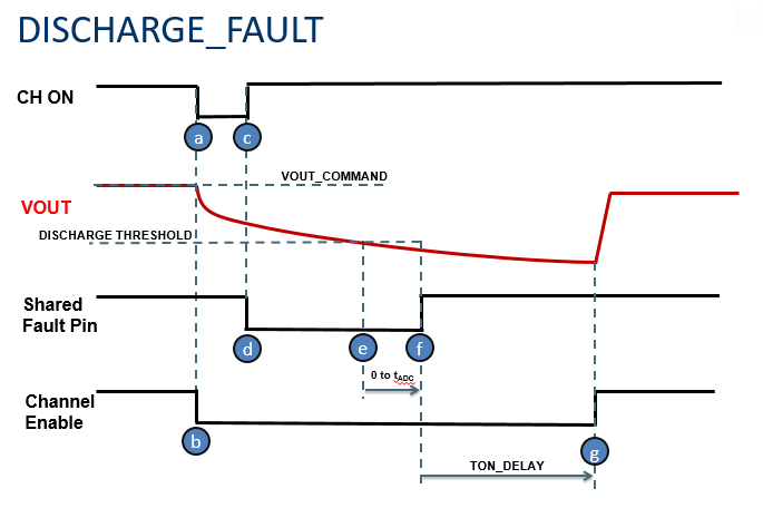
The waveform below illustrates an example discharge fault and associated system behaviors:
The example starts with the device in normal operating mode with no faults. The channel is commanded off and then on by the user. This can be via the CONTROL pin, OPERATION command, or VIN rising above the programmable VIN_ON threshold, or combination thereof, depending on the configuration of the channel. For a clearer understanding of the selected channels on/off behavior, select 'Utilities > On / Off Configuration...' in the menu.
- a – The channel is commanded off. This may be because VIN dropped below VIN_OFF, the CONTROL pin was de-asserted, or the PmBus OPERATION=Off command was issued
- b -- In response to the off condition, the channel's output enable is disabled, typically immediately, though options exist to honor the TOFF_DELAY before disabling (soft off). When using this configuration, the output enable should be connected to a power supply so that de-asserting it disables the managed power supply.
- c – The channel is subsequently commanded back on via VIN/CONTROL/OPERATION or a combination. See the On / Off Configuration tool for a list of requirements for turn on.
- d -- At the time the channel is commanded on, the present ADC reading of the VSENSE pins is compared to the discharge threshold (VOUT_COMMAND* MFR_VOUT_DISCHARGE_THRESHOLD). If the ADC reading (subject to ADC latency) is above this threshold, a DISCHARGE_FAULT is declared. In the case (as in our example) that the channel is propagating faults to a shared fault pin, it will de-assert the shared fault pin signalling the DISCHARGE_FAULT to other channels
- e -- In our example, at this point the VSENSE voltage (at the pins of the device) has decayed below the discharge threshold. However, the ADC is subject to tADC latency (consult datasheet)
- f – When the ADC has measured the VSENSE voltage drop below the discharge threshold (0 to tADC after the physical voltage has dropped below the threshold), the channel is ready to trigger a coordinate re-sequence of the system. It releases the shared fault pin to signal that it is ready, and initiate time=zero of the coordinated resequence.
- g – During the coordinated re-sequence, each channel, after waiting its programmed on delay (TON_DELAY) will start ramping its voltage up
- Controllers have the ability to ramp the voltage directly, and will ramp the output consistent with the programmed TON_RISE setting.
- Managers will assert the assert the VOEN pin to enable the managed supply at this time
This coordination feature insures that when power is toggled or when channels are toggled off/on, each channel is below its required discharge threshold before a coordinated re-sequence is attempted.
Possible Causes:
- Output Enable not connected to managed supply (board or assembly error)
- External device is over driving output enable (i.e. unprogrammed FPGA)
- Too short a MFR_RESTART_DELAY, or toggling off/on too fast
- Discharge threshold too low
Remedies and Workarounds
Here are some things you can try to narrow things down:
- Increase the MFR_VOUT_DISCHARGE_THRESHOLD and see if the problem goes away ( 0.5 means 50% of VOUT_COMMAND, 0.6 meant 60%, etc)
- Disable the MFR_VOUT_DISCHARGE_THRESHOLD ( > 1 is disabled)
- Increase the MFR_RESTART_DELAY to stretch the length of disable pulses on the CONTROL pin
Other Debugging Tips
Check for glitches (quick toggles) on the CONTROL pin. If you have an oscilloscope, perhaps the fastest way to insight is to:
- Probe the VSENSE pins of the IC
- Probe the CONTROL input
- Alternately if CONTROL is not used, probe the output enable signal
Trigger the scope on the falling edge of ALERTB
The ALERT pin will be pulled low at the time of the DISCHARGE_FAULT. If the control pin is toggled too quickly, try the remedies and workarounds above to stretch the interval, or correct the source of the problem. If the output is not disabled when the output enable is de-asserted, check the connection between the output enable and the power supply. There may be a missing or failed connection (cracked resistor, etc).